
Covid-19 has forced us in an extended “staycation”, rather than sitting around watching TV, I’ve been working some electronics projects. Next up, adding some Pinduino action to my Lord of the Rings pinball machine.
Tools Needed
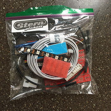
- Pinduino kit – https://pinside.com/pinball/market/shops/1025-professor-pinball
- Soldering iron
- Quality Solder (get Kestler – you won’t regret it)
- Fume extractor fan
What is a Pinduino?
A Pinduino basically adds a little light show to your pinball machine. It basically is a few addressable LED strips that are triggered the pinball machines flasher.
Rather than simply blinking the flasher bulbs, the little programable Arduino board can set off a variety of animations. For example an explosion effect or chaser lights around a ramp.
For Lord of the Rings the idea is to have a strip of lights at the top of the game and two down near the slings.
This video gives an idea of the effects you can get from the program or Arduino sketch provided by Pinduino. You can also customize your own effects with a little programming.
Assembling the board
I saved some money and purchased the unassembled board and components. It’s not hard at all to solder the components on to the circuit board and Pinduino provides step by step instructions.
Do pay attention to the headers. I got distracted and ended up soldering them on the wrong side of the board. I wasted time unsoldering them and redoing them.


First components on. Careful not to bend any pins. I probably should check my work with a magnifying glass but the Kester solder flowed nicely.
The white rectangles are optocouplers – An opto-isolator is an electronic component that transfers electrical signals between two isolated circuits by using light. Opto-isolators prevent high voltages from affecting the system receiving the signal.
How cool is that? No connection – just light.
The black bars are resistor banks.
A resistor is a passive two-terminal electrical component that implements electrical resistance as a circuit element. In electronic circuits, resistors are used to reduce current flow, adjust signal levels, to divide voltages, bias active elements, and terminate transmission lines, among other uses.
You will find a lot of resistors in electronic projects. Often they are single ones with colored bands. The colors are a code used to look up their value.

Here is the receptor for the nano which will be the brains of the operation. The nano is a programable board which will store and execute the light show program.
The program will sense voltage going to the flasher lights and then run a couple of addressable led strips to provide lighting effects.

Ok, slight set back as I soldered the two connectors on the wrong side!
No biggie except for some time wasted using a solder extractor to remove the pieces and resolder.
All connections for power and LEDs attached. Nano put into place.

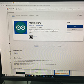
Now I have to download the software (Arduino IDK) and the Pinduino Sketches to the Arduino Nano via the PC.
The Arduino IDK is the developing environment. Software in which you can write programs (Sketches) and download to the Arduino.
I also downloaded the drivers needed for the Arduino.
The settings (under “Tools”) within the Arduino IDK for my set up turned out to be:
Board: Arduino Nano
Processor: ATmega328P old bootloader
Com port 5
You can figure out the com port by disconnecting the Arduino and checking the Com Port list under Tools. The plugin the Arduino and see which com port gets added.
I ran the simple “blink LED” Arduino test sketch to see if everything was OK.
Power for the LED strips
“It is powered from the Aux plug near the coin door. The arduino is powered from the 12V+ and doesn’t draw much power. The LEDs are powered by the 5V+. Each LED draws about 50mA when set to white (all three channels) and at 100% power, and this set up uses ~50 LEDs. So if all LEDs are set to white on 100% brightness, it draws about 2.5A. This set up usually is drawing a third of that as most of the color effects are red or green (some yellow and orange). “
https://pinside.com/pinball/forum/topic/interactive-led-lighting-for-lotr
This setup has a strip of LEDs along the top of the playfield’s back panel above where the lights mount and two strips on the front on each side of the apron.
Complete install instructions for Pinduino Lord of the Rings can be found here: https://docs.google.com/document/d/1flqpWpg-yn98aAIjPoJgZX-o_H5LMovO5QdyXzAD88U/edit
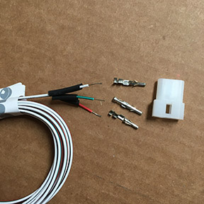
WARNING: Don’t screw up the AUX connection like I did. First I put the pins in the wrong way and had to order a pin extractor to get them out.
Then I got distracted and hooked up the 12V to the GND by mistake. This blew a fuse, a few transistors and chip on my driver board. I had to send it to Allen Davidson, the best in the biz:
Allan Davidson
80 Fox Run Rd
Bellingham, MA 02019
I wrapped the boards up in tin foil and bubble wrap on a Monday and by Thursday he had already fixed the problems. Cool thing – Allen was the first owner of my Lord of the Rings.